Graph-based representation of microstructure
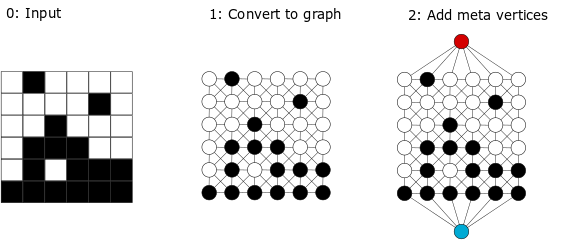
The package is built on the concept of graph-based microstructure representation. The segmented and digitized morphology is represented using a labelled, weighted, undirected graph. Each pixel (or voxel in 3D) becomes a graph vertex with a label denoting its phase. The vertices are connected with edges that capture information about distances. Graph construction for simple two phase morphologies is illustrated in figure. Once the morphology is represented as a graph, the standard graph-theory algorithms are used to quantify information about shortest paths and connectivity.

Digitized and segmented morphology is the input to the software. Graph construction of a labeled weighted undirected graph \(G = (V,E,W,L)\) for a two-phase, two-dimensional morphology is described in this section. A vertex \(v \in V\) corresponds to an individual pixel (voxel in 3D) in the morphology. Each vertex \(v \in V\) is assigned a label \(L(v)\) of BLACK or WHITE, depending on the phase of the respective pixel. Vertices are connected via a set of edges \(E\). The inherent structure of the morphology (pixel locations on a uniform lattice) is used to construct the set \(E\). For each pixel in the digitalized morphology, the local neighborhood is established. For example, a pixel can have 8 neighbors in 2D and hence a vertex corresponding to a pixel can have up to 8 neighbors in the graph. An edge between a pair of vertices correspond to neighboring pixels positions. Each edge \(e=(u,v) \in E\) is assigned a weight \(W(e)\) equal to the Euclidean distance between the pixels corresponding to \(u\) and \(v\) in the morphology. First order neighbors one lattice distance away have an edge weight of \(1\), second order neighbors \(\sqrt{2}\) lattice units away have an edge weight of \(\sqrt{2}\) weight. For 3D systems, third order neighbors are included. To facilitate the graph descriptor computations we introduce the edge labels \(G = (V,E,W,L,L_e)\) (in addition to the vertex labels \(L\)). The edge color set consists of: \(f, s, t\), that correspodns to first, second and third order descriptors.
The graph \(G\) can be constructed for several types of data. In Figure, the graph construction is showcased for three types of data: structured two-phase morphology, structured three-phase morphology and unstructured two-phase morphology. To address various types of data GraSPI offers two options to input data required to construct the graph. The first option allows to read the structured morphologies and can be used when the phases of the input morphology are discretized on a structured grid. Here, the neighborhood is well defined and edges and vertices are simultaneously created and added to the graph. The second option corresponds to unstructured data. In this case, the data is read from the input file according to the internal format described in the appendix. This option allows to handle unstructured data sets where the neighborhood is location specific and needs to be determined externally (e.g., using Voronoi diagrams of knn-algorithm).
In the second step, more meta-vertices are added to the graph. For OSC morphologies, two types of meta vertices are added. The first type facilitates information extraction with respect to the electrodes: anode (red vertex) and cathode (blue vertex) (see Figure Step 2). The second type extracts information about the interface (green vertex). For two-phase morphologies, there exists only one type of interface between BLACK and WHITE vertices. This interface is tracked and the edges that connect a BLACK and a WHITE vertex are deleted, and subsequently connected via an added meta-vertex (green Once edges are added to the meta-vertices, weights are assigned to them. Edges of weight \(W=1\) are added between the anode/cathode and the vertices \(v \in V\) (which correspond to pixels) physically adjacent to the anode/cathode. Additionally, edges of weight \(0.5\) are added to represent the connections between the interface vertex and the BLACK/WHITE vertices, \(v \in V\). If \(v\) with \(L = BLACK\) and a \(v\) has an edge of or \(L = WHITE\) has an edge of weight \(1\) to another \(v\) with \(L = WHITE\) or \(L = BLACK\). The anode, cathode, and interface vertices have labels anode, cathode, and interface, respectively. The added vertices allow for a straightforward estimation of graph distances from any location on the domain of the morphology to the electrodes.
Once the graph is constructed, its quantification becomes independent of the original dimensions(2D or 3D) or type structured or unstructured). The morphology quantification is recast as graph query (Step 3 in Figure). The graph queries relies on algorithms from graph theory, e.g. Dijkstra algorithm, connected components that we describe in the next subsection.